
HI-TANK is world-class quality GRP water tank with ISO 9001:2008, Singapore PSB, UK WRAS and US NSF certification
GRP SECTIONAL WATER TANK
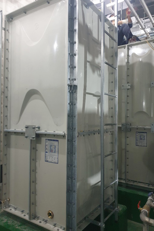
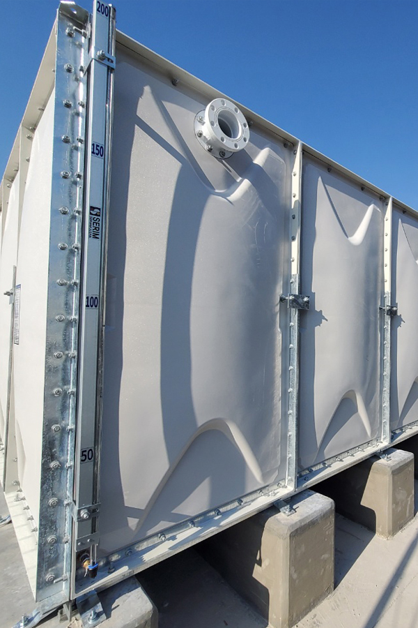
HITANK utilizes SMC (Sheet Molding Compound) molding technology which is reinforced from Unsaturated Polyester resin and glass fiber, based on technology for years, our quality as to manufacturing for small, medium and big water tanks has been highly regarded.
Hi-tank satisfies 100% condition of hygiene, watertightness, durability which is required for SMC water tank. Thanks to this high-accumulated technology, this water tank is certified by ISO 9001, SINGAPORE PSB, UK WARS, therefore this quality has a world-class guarantee.
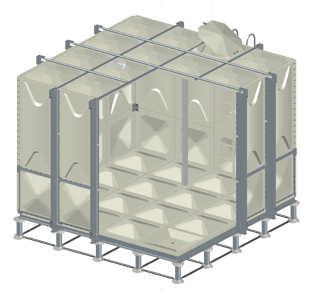
External
Reinforcement
System
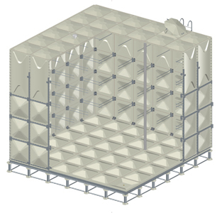
Internal
Reinforcement
System
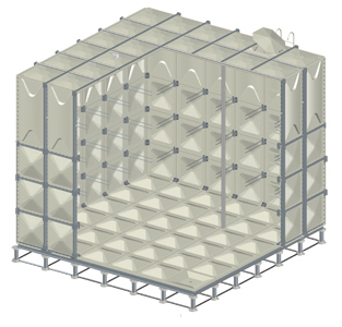
Combined
Reinforcement
System
Characteristic
HITANK uses GRP (Glass Reinforced Polyester) fabrication technology reinforcing unsaturated polyester resins and glass fiber and, based on technology accumulated for a number of years, is widely recognized for its technical capabilities in the quality manufacturing of water tanks in all sizes and capacities.
HITANK fully satisfies the conditions of sanitation, watertightness and durability required for an GRP water tank. Based on such advanced level of technology accumulated, it guarantees world-class quality having acquired several global certifications including ISO 9001, PSB of Singapore and WARS of the United Kingdom.
The external forces used in the structural design of water tanks are as shown in Table 1 below, and they must be designed by considering all combinations of stresses generated.
1. Combination of design external forces (loads)
| Types of stresses | Expected state/condition | Weight of internal water (F) | Dead load (G) | Snow load (S) | Live load (P) | Earthquake load (K) | Wind load (W) | Remark |
|---|---|---|---|---|---|---|---|---|
| Long-run | At all times | ○ | ○ | Footnote 2) | - | - | - | - |
| Short-run | When loading | ○ | ○ | Footnote 2) | ○ | - | - | - |
| In case of a storm | ○ | ○ | - | - | - | ○ | Footnote 1) | |
| In case of an earthquake | ○ | ○ | Footnote 2) | - | ○ | - | - | |
| In case of snow | ○ | ○ | ○ | - | - | - | - |
Footnote 1) It is deemed that there is no internal water when reviewing buckling due to an external force by a storm, conduction or fixed parts of the basic frame.
Footnote 2) When installing in a region with heavy snow, the snow load is regarded and added as a Long-run load, or as a Short-run load when loading. In case of an earthquake, combine the load and consider a suitable snow load for the installed area.
Horizontal seismic coefficient, KH, is a coefficient determined by the area in which a water tank is installed, the importance of the water tank, building structure, installed floor, etc. Typically, its formula is as follows.
· KH = β * KFH ≤ 2.0
· KFH=I * K1 * Z * KOH
※ β: Acceleration response magnification ratio of the water tank during an earthquake / KFH : Horizontal seismic coefficient on the nth floor / I : Strength coefficient of building use (importance factor of a building or water tank) / K1 : Coefficient depending on the floor on which the water tank is installed / Z : Zone coefficient/ KOH : Horizontal seismic coefficient applied on the 1st floor (=0.4)
| Floor on which the water tank is installed | β |
|---|---|
| Underground or 1st floor | 2.0 |
| Rooftop floor | 1.5 |
| Category | β |
|---|---|
| When shock resistance is particularly emphasized | 0.7 |
| When shock resistance is emphasized | 0.5 |
| Others | 0.3 |
| Category | β | Remark |
|---|---|---|
| Underground or 1st floor | 1.0 | * ai = ( N+2- i ) / N+1 ※ N: Number of ground floors of a building (rooftop floor is N+1) i: Floor on which the water tank is installed |
| Rooftop floor | 2.5 | |
| Middle floors | 1/ ai ≤ 2.5 |
※ I *z= 0.5(I=0.7) / I *z= 1.0(I=1.5)
| Upper floors Rooftop and loft | 0.7 | 1.5 |
|---|---|---|
| Middle floors | 0.5 | 1.0 |
| Underground 1st and ground floors | 0.5 | 1.0 |
* KH is set as 1/3, 1.0 and 3 of 1.5, which have been rounded up.
Hydrostatic pressure by the internal water is treated as a Long-run load and calculated by the following formula.
Ps = 0.1 X y
※ Ps: Hydrostatic pressure (kgf/cm²) / y : Distance from the water surface (m)
However, the maximum level of the internal water shall be the height from the floor of the water tank to the level of overflow.
Snow load on the ceiling of a water tank is treated as a Short-run load, and the snow load for standard design shall be S = 60kg/m².
For reference, it is 1) 2kg/m²/cm for common regions, and 2) 3kg/m²/cm for regions with heavy snow.
Live load (P) is the weight of persons on the ceiling, assumed as a concentrated load and treated as a Short-run load. (P=80kg/panel)
Fixed load (G) is the weight of a water tank’s main body and treated as a Long-run load.
For a water tank installed outdoors, the wind load shall be considered and is treated as a Short-run load.
| Location | Wind pressure, p (kgf/m²) | Wind load, D (kgf) | Remark | ||
|---|---|---|---|---|---|
| Installed location | Installed location | ||||
| Ground | Rooftop | Ground | Rooftop | ||
| Side of water tank | 96 | 225 | 144 × A | 385 × A | * A : Area on which the wind pressure force is exerted |
| Ceiling of water tank | -96 | -225 | |||
Structural design of a water tank basically obeys the following formula [Allowable stress = Threshold / Safety factor ≥ Applied stress] For thresholds, the following two types are considered.
1) Permanent deformation: Based on the stress at the proportional limit point on a stress-strain curve
2) Fracture strength: SMC is difficult to define a proportional limit stress, thus the ultimate stress as the fracture strength is employed.
1) Safety factor for fracture strength of SMC material (F₁) : F₁ = 2.2
2) Safety factor in case there is an issue with the elastic modulus of SMC material (F₂) : F₂ = 1.87 (Safety factor of reinforcing structural steel and materials other than SMC is set as F₂= 2.0.)
For common properties of SMC as shown in Figure 3-1, the degree of deterioration by the changes of SMC in the next 15 years is small so 60-70% of the initial static characteristic value (at room temperature) was applied as the threshold (strength), and, for permanent loads such as hydrostatic pressure and fixed load that are applied at all times, a safety factor that is 1.5 times greater (than that of a temporary load) was additionally multiplied.
| Fracture strength | Unit | Initial characteristic value (at roomtemperature) |
Threshold considering 15 years of service life | Allowable stress | |
|---|---|---|---|---|---|
| Temporary load(*1/2.2) | Permanent load(*1/2.2*1.5) | ||||
| Tensile strength | kgf/mm² | 10 | (*0.7) 7.0 | 3.18 | 2.12 |
| Flexural strength | ‥ | 16 | (*0.6) 9.6 | 4.36 | 2.91 |
| Elastic modulus | - | - | - | - | - |
| Tensile modulus | kgf/mm² | 900 | (*0.8) 720 | - | - |
| Flexural modulus | ‥ | 1,200 | (*0.8) 960 | - | - |
| Poisson's ratio | - | 0.3 | 0.3 | - | - |
| Fracture strength | Unit | Allowable stress | |
|---|---|---|---|
| Temporary load | Permanent load | ||
| Tensile/compressive strength | kgf/mm² | 24 | 16 |
| Flexural strength | ‥ | 24 | 16 |
| Shear strength | ‥ | 13.5 | 9 |
| Elastic modulus | kgf/mm² | 900 | (*0.8) 720 |
| Young’s modulus (E) | kgf/mm² | 21,000 | 21,000 |
| Poisson’s ratio | - | 0.3 | 0.3 |